Modelling simple AB air brake systems on your freight cars
Introduction
This article is a part of the RailBox XAF10 class series of articles from Andrew’s Trains. While not an exact replica of the cars (for a couple of major reasons) they are cheap, easily available on the used market (often new and incomplete) and with a little work turn into a great model in their own right.
Overview
This article provides a method to model the brake rodding of an AAR AB air brake system to get the maximum look with minimum effort. Train lines and brake-system piping exist on all freight cars; the design of many car types (especially boxcars, flat cars, and gondolas) makes it difficult if not impossible to see in regular operation. Providing simplified brake gear without all that piping, and the time and materials required to install improves the look of your freight fleet and can be done in a short time (usually an hour or so).
A quick word of thanks
I’d like to thank Tony Thompson from the ‘Modeling the SP Blog’ who was the inspiration for this article. (See the Resources section at the bottom of this page for a link to Tony’s original blog post.) Tony’s minimalist brake line modelling omits piping and any other items of brake gear that are out of site on freight cars as we would ‘normally’ view them. Tony’s approach makes sense on a running model; after all if you can’t see it then why should you model it?
My models are not contest entrants, they’ll never win trophies, and they’ll be unlikely to ever run anywhere else except on my layouts. I recommend that you read Tony’s entire article before beginning your own minimalist brake system journey. Tony does make a couple of valid points early in the article that I’d like to share with you before we begin adding representative brake gear. He writes:
“…simplified brake gear is definitely less appropriate for tank cars and hopper cars (including covered hoppers). They are different in that the piping is visible on an upright model, so in those cases I would include it. I would also normally include enough of the brake rodding to be noticeable in a side view. That “side glimpse” is what I want to reproduce on most cars, though any car with a fish belly side sill will conceal even that much of the brake system. Sometimes I even omit rodding…”
Understanding what we’re modelling
I’m modelling the rodding (the mechanical linkages) used to work the brake system from the brake cylinder to the trucks. I’m not modelling the rest such as brake lines, slack adjusters (although they are easy to model if you choose to do so), nor am I modelling the hand brake assembly beyond representing the rodding for it.
In addition I’ll be modelling the lever carriers and rod carrier as these hang down from the underframe and are noticeable on the XAF10 class cars and indeed most types of boxcar.
You can see the entire AB air brake system depicted in Image 1 below.
Image 1: AAR AB Air Brake system layout (Image courtesy of: www.intellirail.com)
PLEASE NOTE: Any errors in execution or design with this project are my own.
The basic model
I’m using the Athearn BB kits 5520 (undecorated) and 5521 (Railbox) for this build (they’re the same kit in all other respects). Most model underframes have some representation of the brake gear. Your mileage will vary depending on the manufacturer and car chosen.

Image 2: the as built underframe with parts labelled
To build a set of simplified brake gear, the basics parts are included on the Athearn underframe. The three core elements of an AB brake system are the:
- reservoir,
- control valve and
- brake cylinder.
You can see them moulded (in all their lumpy finery) in Image 2 above. I am not building a contest grade model. I do not need to be able to count the number of bolts, see welds or threads on the fittings on any individual part. I am looking for an artistic representation of the parts and the ‘sense’ of the workings under the floor of the model while it is in regular operation. This is as much a mechanical art project as it is one of material science.
Initially I planned to use 0.012″ thou brass for the brake rodding. Not having enough to complete the work I opted instead to use 0.020″ brass rod in its place. I am glad that I did. The larger diameter rod has worked well and is not as prone to bending and handling damage as the thinner ones. I find too that the 0.020″ brass looks just right for the job once painted. If however, you want to use the finer brass rods in either the 0.012″ or 0.015″ range, by all means knock yourself out.
If you were deciding to go all out and make a contest model I’d suggest though that you use the finer diameters for the air-lines. This would provide a level of visual differentiation between the moving (mechanical) parts and the static air brake piping.
Tools and supplies
There is some clean-up work to do, this is not too difficult and does not need special tools. For the entire project you’ll need:
- 020″ thou brass rod, or something similar in the Evergreen plastic’s range (you can use premade grab irons or staples if that is what you have)
- I’ve used regular staples for the carriers (as used in a garden variety stapler)
- A sharp #17 lightweight chiselling blade and an Exacto style handle to wield it in
- Superglue (your choice) – I prefer to have thick superglue for this use
- Wire cutters ( to cut the brass)
- Pliers (to aid in bending the brass wire)
- A small mill or other metal file to clean up rough edges of the cut brass
- Small hobby drill set, and
- A pin vise
Creating the basic brake gear
This is a straightforward three-step process:
- Mill the unwanted moulded detail from the underframe
- Drill the holes in the underframe for the rodding and retainers
- Cut, bend and glue the rodding and retainers in place
We’ll work through the steps one at a time. Once you’ve completed the first car you’ll be able to work on each step in batches on any remaining cars you have. This will definitely speed up the work. I do recommend working on a prototype car first though before going the full Monty.
Step 1 – Milling the underframe
There is not a lot to do in this step.
- You need to remove the moulded retainers from the underframe. These are the lines crossing over the levers on the underframe, and the moulded rod between the levers.
- Use your #17 blade in your knife handle for this.
- Take your time and work with the blade inverted; that is the flat of the blade (the bottom) should be facing up, while the chisel side (the top) of the blade is facing the work.
- This just ensures that you cannot dig too deeply into the plastic as you are working.
- When finished your underframe should look like my underframe shown in Image 3

Image 3: The underframe work in progress – milling and drilling
Step 2 – Drilling the underframe
Step 2a – Drilling the carrier holes
I use a #73 (0.024″ clearance) drill for both the staple and brass fittings. (While rare, in this case one size does fit all). As you’ll note from Image 3 above I was still working on drilling the underframe when taking the photo.
I recommend that you drill the underframe for the lever carriers first. Use the outer edge from the moulded retainers that you’ve just removed to locate and drill them.
In the case of the rod carrier (which I added after some study of the AAR AB air brake drawing) I’ve used creative license, as the Athearn frame does not provide a mounting location.
I chose a spot roughly halfway along the rod run for locating a carrier (shown as a staple) on the prototype car (see Image 4 below). This is a logical place to locate the rod carrier, as the maximum deflection of the brake rod would be around the middle of the run.

Image 4: Location of the rod carrier as shown on the prototype car
With the carrier holes drilled it’s time to move onto drilling the brake rod holes.
Step 2b – Drilling the brake rod holes
There are five holes required for the brake rods as shown in Image 5 below for:
- The connecting actuator rod, A and B ends (along the centreline of the underframe), and
- Brake rod mounting holes shown as ‘brake rod’ in Image 5 below

Image 5: The brake rodding holes to be drilled
Take your time while drilling. If you need to, start with a smaller pilot hole (using a #78 drill) before moving up to the #73 drill. We’re drilling small holes in small pieces of plastic with little room for error. No pressure, mind you.
Be especially careful while drilling the brake rod hole on the lever nearest the brake cylinder. Ideally you should ensure that the cylinder arm and the brake rod align as closely as possible. Depending on your level of comfort and skill in drilling the hole can be either:
- On the dimple where the brake valve arm joins the lever (shown in Image 1 above), or
- Just inboard of the connection between the brake valve and the lever (shown in Image 5 above)
I’ve drilled just inboard because I’m using the 0.020″ thou rod. Using finer brass rod would I think enable you to drill right to the edge of the lever. I chickened out because I was concerned that the lever end could break off.
Whichever path you choose make sure to take your time and that you centre your holes in the body of the lever.
Step 3 – Cutting, bending and gluing
I’m assuming that you’ve never upgraded freight cars using brass before. Each step provides you with the knowledge and skills you need to complete the task. If you’ve already done similar work in the past then skip through the descriptions and take what you need from the text to complete the task.
There are two parts to this step:
- cutting and fitting the brake rods, and
- cutting and fitting the carriers.
Both steps are easy and go quickly once you get into the rhythm of measuring, bending, and gluing.

Image 6: Brake rodding runs required
Step 3a – Brake Rods
There are four brake rods to be cut, bent, and glued in place.
We’ll start with the actuating rod between the two levers:
- Using your pliers bend a 90 degree angle in your brass rod. This need only be long enough to pass through the lever
- Placing one leg of the actuator rod into the centre of the lever, measure by eye where the other bend needs to be, and move your pliers to that point,
- Using finger pressure, bend the rod around the nose of the pliers to 90 degrees,
- Test the fit, and when satisfied cut the long leg of the rod. This only need to be long enough to pass through the lever,
- Dip both ends in a puddle of super glue and place carefully in the holes
Next we’ll work on the three brake rods:
- Using your pliers bend a 90 degree angle in your brass rod. This need only be long enough to pass through the lever
- Placing the formed brake rod end into the lever and measure to a point just past the first (inner) axle of the bogie (leaving a 3mm (around an 1/8″) overhang ensures that your rod disappears behind the bogie),
- Cut the rod to the desired length, and
- Dip the 90 degree bend into your puddle of Superglue before placing carefully in the hole in the lever, and
- Repeat for the remaining brake rods.
A couple of notes for you:
- You’ll need to leave the car on its back while the glue sets up. This will ensure that your brake rods go where you want them to go. This is the reason I prefer thick Superglue – setting time. I can move items about until they are perfect before the glue sets up,
- Glue the hand brake rod, on the far end, to your underframe. It should not remain hanging on the axle like the other two brake rods. This is because the hand brake rod attaches to the bell crank mounted on the end of the car.
Step 3b – Carriers
- Using a pair of pliers peel a staple from your strip of staples.
- Placing one leg of the staple into one of the rod holes, measure by eye and move the nose of your pliers to the point where you want the bend.
- Using finger pressure, bend the staple around the nose of the pliers to 90 degrees.
- Cut both legs to shorten them to fit the depth of your drilled holes.
- Dip both ends in a puddle of super glue and place carefully in the holes
- Push the carrier into place.
- Repeat until all the carriers are completed.
Takeaway
This concludes the article “Modelling Simplified Brake Systems on freight cars.” I hope that you’ve enjoyed the build article and that you enjoy the results. I know that my boxcars are looking better every time I see them. This type of upgrade, that cost little in terms of time and money, make a big visual difference and are what I am working toward in my modelling. Check out the before and after photos to give you an idea of the difference:

Image 7: An Athearn BB XAF10 class car without brake rigging

Image 8: An Athearn BB XAF10 class car with brake rigging
While at first glance the brake rodding doesn’t look to my eye at least perfect, once it is weathered and in context with the remainder of the model, I feel it will look just fine. To that end here is an image of a car with the weathering completed to show what I mean:
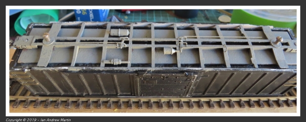
Image 9: Weathering begins to tone down the rodding
Already you can see that the rodding stands out less, is more in context with the underfloor detail, and looks the part. The next photo shows another car with the same treatment as the one above, but this time with car weathering in place and with full as running context:

Image 10: This Southern boxcar with weathered underframe looks the business
The southern boxcar above looks the business, and when the XAF10 class build is complete they’ll also have a better look to them from trackside showing the underframe gear without it being a standout on the model.
Please make sure to like and subscribe to the blog (if you haven’t already). Comments are always welcomed. I try to answer every one within a week.
Resources
Websites:
- Tony Thompson’s Modeling the SP blog post on modelling brake gear.
- Other websites as mentioned in the text.

You must be logged in to post a comment.